It turns out that you can buy the LED panels that are used in big advertising boards or the big screens at festivals, and they weren't that expensive so I bought 4!
The panels that I bought are compatible with the HUB75 protocol. This protocol is less of a protocol and more a name for the driving procedure. The panels have a shift register that you clock the data into, and then enable the output once all is shifted in to display the data. Each LED has three registers, one for each pixel.
The pixels are then put in rows of 64, of which there is 192 of them. Using the Row Select lines A-E and the 6 RGB lines, two rows of LED data can be shifted in at once.
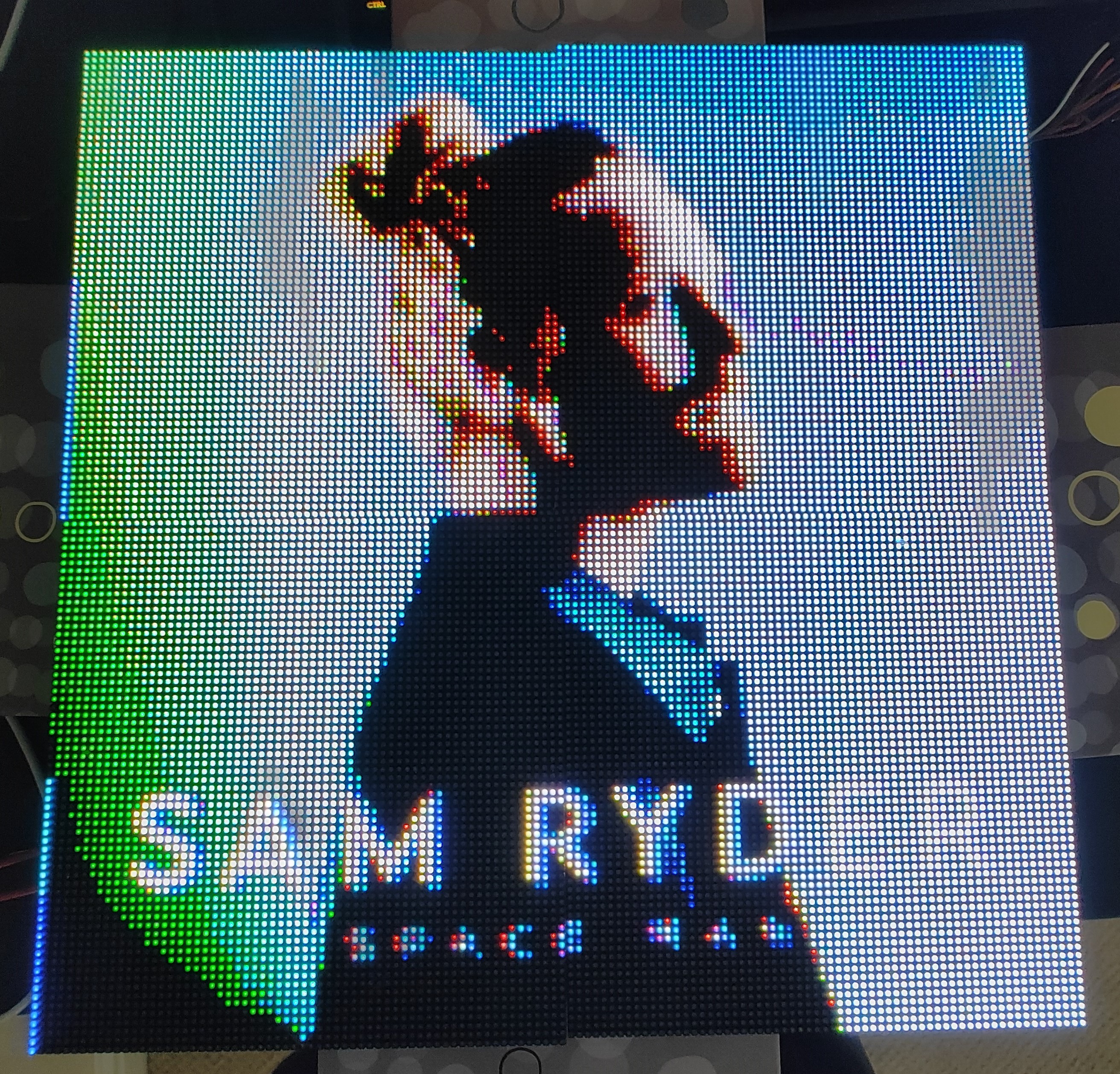
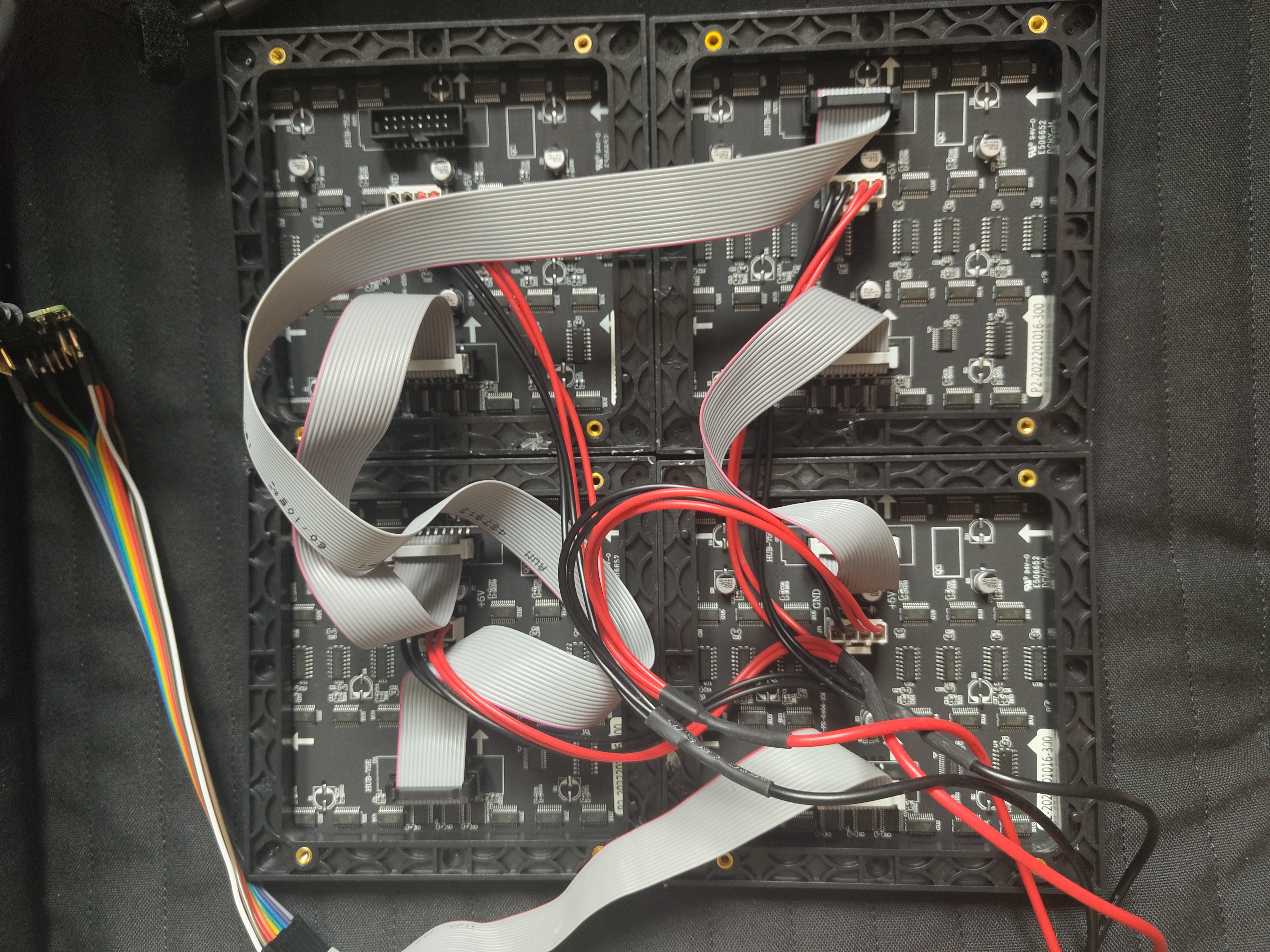
I have then arranged my panels physically in a 2 by 2 configuration to give me a display with a resolution of 128 * 128, but electrically they have been daisy chained together.
As the pixels can only be turned on or off, there are only 8 possible colours for each LED. Each pixel can be pulse width modulated to have it more on or more off over time to adjust the perceived brightness of the colour. I am using 5-bits 0-31 for pixel brightness. This means that I can fit 6 pixels worth of data and two control bits into a 32-bit word.

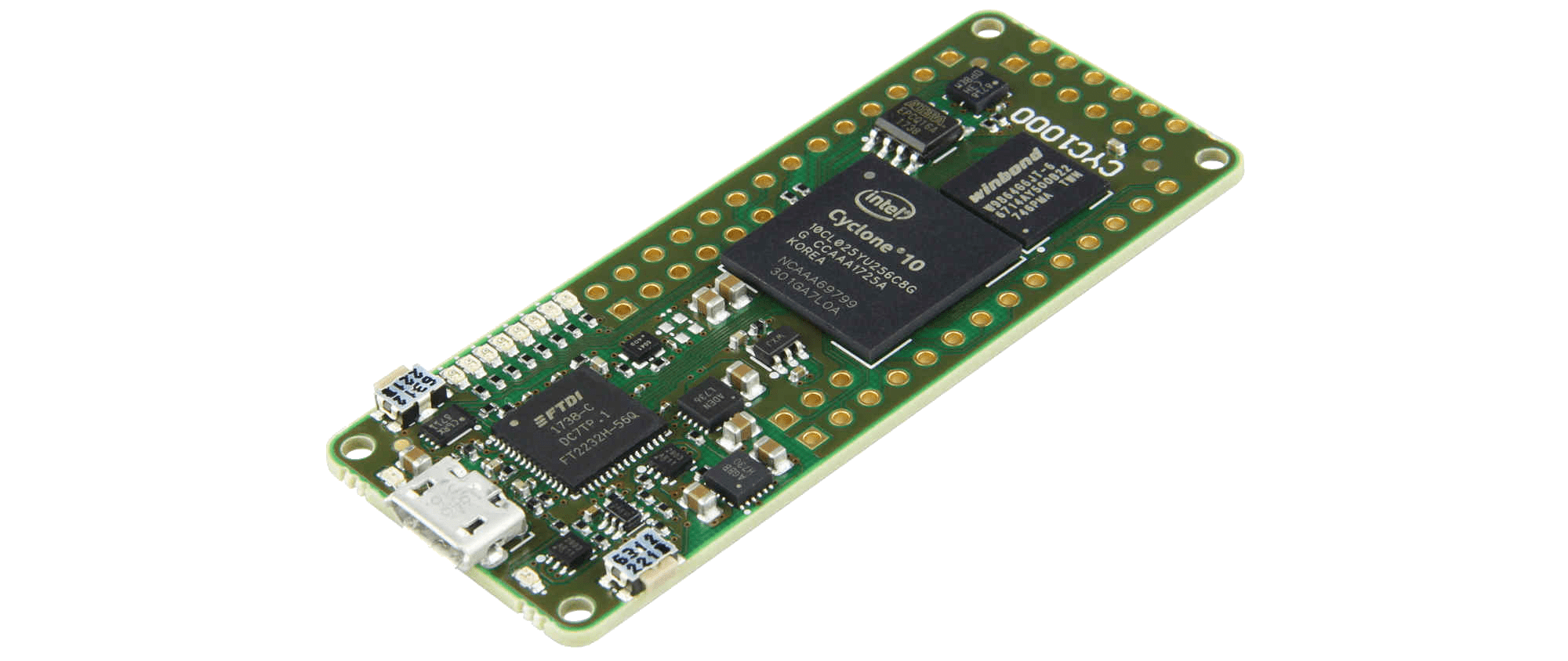
As only two rows can be illuminated at a time, the illuminated row needs to be cycled so it looks like all of them are illuminated. Given that they also need to be PWMd I need as much speed as I can get. Thus I used a cyc1000 FPGA dev board that I had.
As this is an FPGA, it can have multiple processes running concurrently. I have one loop that receives display data over UART, and a process that drives the display. This means that the display doesn't stop displaying an image when receiving a new one.
The driving loop is a Finite State Machine(FSM) that goes through the stages of shifting data down the panels.
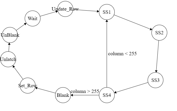
It shifts all the data into the register until all 256 pixels (4 64 wide panels in series)have been set, it then turns off the display, sets the correct row and displays the new data.
Using the serial port tool that I made in my last blog post I was able to make a module that sent raw hex values to the display to be shown as an image. Here's a sneak preview of the smart display.